 EN
EN  VI
VI  JA
JA An excellent design is not just about the product functioning well, but also about meeting the criteria of being easy to manufacture at the lowest possible cost. In the mechanical engineering industry, this concept is known as DFM (Design for Manufacturing). When transitioning from making a few prototypes to mass production, even a small design error can significantly increase material and labor costs.
Below are 5 golden principles in mechanical product design that help businesses optimize machining costs effectively, distilled from thousands of real-world projects at Metaltech 1 factory.
1. Optimize the workpiece shape for easier handling. stacking blanks
Material costs typically account for the largest proportion of the cost of sheet metal products. To save costs, design engineers need to visualize how their components will be nested on a standard sheet of steel (e.g., 1.5m x 3m) before feeding them into the laser cutting machine.
- Avoid overly long L-shaped or C-shaped designs: These details often leave a lot of unusable "dead space" on the workpiece. If possible, separate them into two straight pieces and join them together using a notch or welding.
- Take advantage of the common cutting line: The edges are designed so that when the workpieces are aligned in the software, two pieces can share a single cutting line. The laser machine only needs to run one line instead of two, minimizing machine run time and significantly saving on decal material.
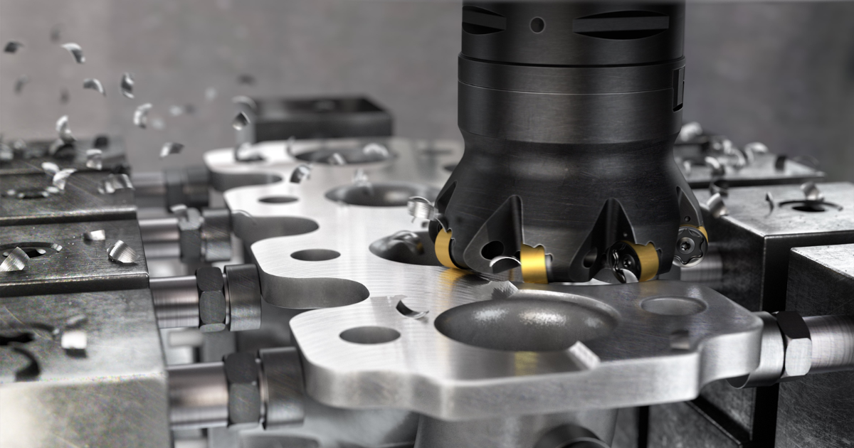
2. Standardization and uniformity of bending radius
In CNC bending, every time the material thickness or inside radius is changed, the machine operator has to spend 10-15 minutes disassembling and reassembling the punch and die assembly.
- Optimization principle: Use ONE bending radius for all folds on the same part. Ideally, design the inner bending radius (R) to be exactly the same as the sheet metal thickness (T).
- This allows the part to be placed on the bending machine only once, eliminating the need to change tools, minimizing processing time, and thus reducing labor costs to the lowest possible level.
3. Minimize difficult weld seams and design self-aligning joints.
Welding is one of the most time-consuming and labor-intensive processes, and it is also prone to warping due to heat.
- Replace welding with bending: Whenever possible, design a single piece of metal to be bent into an angle instead of cutting two pieces apart and welding them together.
- Male and female clamp design: If welding metal plates or pipes is necessary, design additional mounting tabs and slots. These tabs help the parts lock together securely and squarely, saving the welder time on measuring or fabricating complex jigs.
- Avoid sealing unless necessary: If the product does not require handling liquids or high pressure, opt for stitch welding instead of continuous welding. This reduces welding time and limits thermal deformation.
4. Loosen tolerances in areas not used for assembly.
A very common mistake made by new engineers is setting extremely strict tolerances (e.g., ± 0.01mm) for the entire size of the product. The tighter the tolerances, the more expensive machinery the workshop has to use, the more time is spent on adjustments, and the higher the rate of defective (scrap) workpiece rejection -> leading to very high machining costs.
- Principle: Tight tolerances should only be applied to shaft holes, mounting jaws, or direct contact surfaces (mating surfaces). For external dimensions, overall length, or free edges, use standard tolerances (± 0.5mm) to facilitate machining.

5. Standardize drilling holes and safety distances.
- Use standard hole sizes: Don't design a 6.35mm diameter hole if a 6.0mm or 6.5mm hole can perform the function just as well. Using standard sizes makes it easier for the workshop to utilize readily available drills/tapes on the market.
- Distance from hole to edge of indentation: When designing sheet metal, ensure the distance from the center of the punched hole to the nearest crease line is greater than 2.5 times the material thickness. If the hole is too close to the crease, when pressed down, the round hole will be stretched into an oval shape and will no longer be able to accommodate screws.
Metaltech 1 – Optimizing drawings and minimizing costs for businesses.
A design is judged not only on its computer screen, but also when it is put into production as quickly as possible, with the fewest errors and using the least amount of materials.
As a leading integrated mechanical processing plant in Dong Nai, Metaltech 1 is more than just a manufacturing unit. Our team of experienced engineers is always ready to sit down with partners, analyze drawings, and propose DFM improvements to help your project optimize processing costs right from the initial stages.
Do you have a new design and are about to enter the mass production phase? Let us help you review it one last time!
